ADDRESS
-
3A, Type-1, Kukatpally
Industrial Estate
Hyderabad 500072 TS India - cnc@cnctechnics.com
- www.cnctechnics.com
- +91-40-23078000
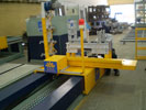
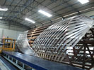
Basic filament winding machines have two axes of motion — the mandrel rotation and the carriage travel. These motions work together to create accurate, repeatable composite windings. The main movement axes are described below:
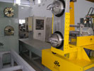
The mandrel rotates around its spindle. This rotation is essential for distributing the filaments evenly and creating the primary hoop or helical patterns.
A carriage that holds the filament payout head moves linearly along the length of the mandrel. This movement is used to lay down fibers in the desired patterns, like helical or longitudinal (hoop) windings.
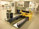
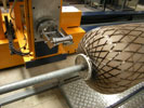
This axis provides movement to the filament delivery system itself. In a 4-axis machine, this traverse is typically perpendicular to the carriage's linear motion and may involve a radial movement across the mandrel's face or a rotary movement of the payout head.
The fiber delivery head can rotate. This provides an additional degree of freedom, which is critical for controlling the angle at which the filament is applied, adjusting the helix angle, and ensuring consistent fiber band width during winding.
Higher-end winding machines feature additional rotation or translation axes for complex geometries and precision-controlled fiber paths — typically used in aerospace, defense, and high-pressure vessel manufacturing.
For Pipe production:
Two axes machines are sufficient. The Axes used are as below:
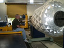
For dome end vessels:
It is advisable and recommended to have a four axes winding machine for products such as CNG, LPG, Low Pressure water filters, etc. The various axes for Dome ended components are as below:
The payout head rotation is used to keep the fiber band from twisting and bunching up. This ensures flat and consistent layup of the fiber during winding. Machines with more than four axes can be used for advanced applications. Six axes winding machines usually have 3 linear and 3 rotation axes.
Machines with more than 2 axes of motion have computer/CNC control. However, two axes machines mostly have numeric control. Computer controlled filament winding machines require the use of software to generate the winding patterns and machine paths. Such software can be provided by filament winding machine manufacturers or by using independent programming sources.
Methodology :
Within a single fiberglass roving, there are microscopic strands. Each strand is coated with a sizing that provides a secondary bonding between the fiberglass strand and the resin. Sizing can be singular resin system compatible, like polyester compatible or epoxy compatible or multi-system compatible, like polyester+epoxy+polyurethane.
The continuous fiberglass rovings pass through a Resin bath where they get coated with a resin or epoxy mix.
Primary material components of filament winding: